Portable phone charger on batteries
Note: See USB phone charger for a more recent version using an USB connector.
Every year I go to the Dutch music festival Lowlands. Since it lasts for several days in which I use my mobile phone a lot the battery is drained quite fast. There is a place where you can charge your phone but endless queues and opening times that never seem to suit you does not make it a great option. So I decided to build my own phone charger that runs on two AA batteries.
Charger requirements
First of all I had to determine what kind of power my phone needed to get charged. The phone is a Siemens S65. The official charger that came with the phone says 5V at 420mA. Because these things do not always actually deliver what is printed on them I measured the voltage myself. This is actually quite hard with the tiny contacts on the connector, especially when it also has to be plugged into the phone. Without a phone connected the voltage was much higher, around 8V if I remember correctly. When the phone was actually connected the voltage would drop to around 4V and even lower.
To do further testing I needed the right connector. An easy way to get these is to find a cheap car charger on ebay. I got this one:
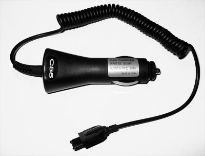
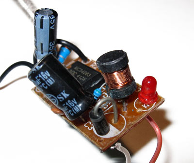
The label says output: '5V-11V DC 350mA'. Of course I opened this thing to look what was inside. I found a cheap looking PCB with a step-down converter based on Motorola's well known MC34063. Based on the component values it was configured for a 8.75V output and a current limit of 320mA. When connected to the phone the voltage drops below 5V because the current limit is reached.
To see at what voltage the phone starts charging I cut off the connector from the car charger and put 5V on it. The phone did not started charging. At 5.5V still nothing, but at 6V it started charging. As was shown with both the official charger and the cheap car charger, once the phone starts charging the voltage may get well below 5V without problems. But it needs around 6V to get started.
Schematic and PCB
To get 6V out of two AA batteries I used a LT1949 switching step-up converter from Linear Technology. An AA battery typically delivers about 1.2V-1.5V but the voltage drops even lower under load and as they discharge. The LT1949 already runs at a voltage of 1.5V so two AA batteries are enough to keep it running, even at low battery voltages. The IC has an internal switch current limit of about 1.1A. This will limit the output current. In fact, the phone tries to use so much current that the current limit kicks in and the output voltage drops below 6V. As the official charger does the same this is not a problem. The current limit is by design and does not harm the IC. The schematic is quite simple and follows the typical application schematic from the datasheet:

The schematic lacks a symbol for the power in and out points (mainly because the PCB layout does not really have any connectors for them) but obviously power goes in on the top left (Vin pin) and comes out at the top right. Low battery and shutdown pins are unused and can be left floating. The part list is short:
| Part | Description |
|---|---|
| IC1 | LT1949 switching regulator |
| C1 | Tantalum capacitor AVX TPS series 22uF 6.3V |
| C2 | Ceramic capacitor 10uF, 10V |
| D1 | Schottky diode 30BQ040 |
| D2 | General purpose Zener diode 6.8V |
| L1 | Inductor Sumida 10uH 2.1A |
| R1, R2 | Feedback resistors (10k/39k) |
I use SMD most of the time anyway but in this case this really keeps everything small. The IC itself has a 0.5 mm pitch and is very small, the inductor from Sumida is relatively small thanks to the high switching frequency (600kHz). The schottky diode could be replaced by something smaller but I had this type lying around, its a pretty good diode. The output is stable with a 10uF ceramic capacitor, I used a panasonic one in a 0805 package. For the input a low ESR tantalum is used from the TPS series. The zener diode is an extra protection, just in case something goes wrong with the step-up converter this diode will provide some protection for my phone against voltages higher than 6.8V.
The PCB layout is also based on the one in the datasheet, the etched and drilled PCB looks like this:

The drilled holes will be used to put some copper wire in that will hold the power wires to the PCB. This way the soldered connections will not break easily if you pull the wires accidently.
Placing the components
Next step was soldering the components (with hot-air) and the wires.

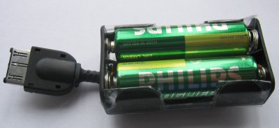
The battery holder, the PCB and the phone connector:
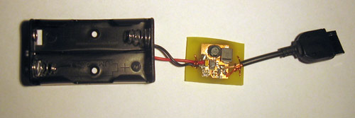
Now, does it work? Yes it does :)
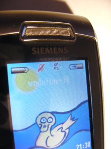
The IC and inductor get pretty warm while charging but not at dangerous levels.
Finishing touch
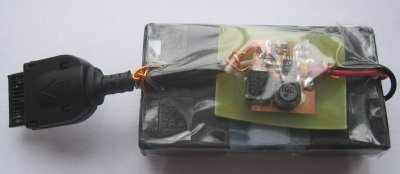
To protect the device from all kinds of dust and water I wrapped it with a piece of adhesive sheet. Okay, it may not look that well but it works great.
Batteries
The first tests where done with regular (non-rechargeable) batteries. I found out that rechargeable batteries work best though, because they can deliver higher currents. The charger consumes about 1A. Normal batteries are best suited for smaller currents. They can deliver 1A but they waste a lot because of internal resistance and run out quickly. Rechargeable batteries have lower internal resistance and work efficiently at 1A. With two 2300mAh rechargeable NiMH batteries, I was able to charge my phone (with 750mAh battery) around 80%.